Pipes/ Branch pipes
If a pipe or a branch pipe is selected, the following properties are displayed in the properties palette: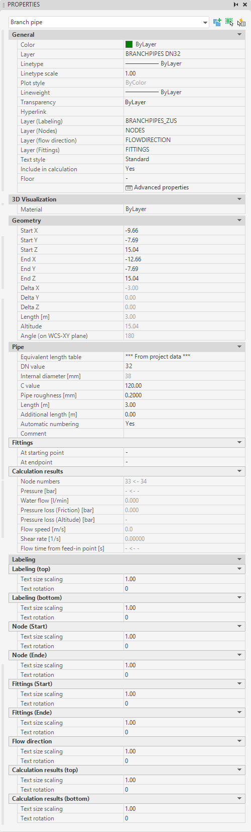
These values can also be transferred, displayed and edited in "Quick Properties" of AutoCAD/BricsCAD.
- Category General, in addition to the AutoCAD/BricsCAD object properties such as color, layer and layer of the labels, the following data of the pipe can be adjusted:
- Include in calculation: If "No" is selected here, this object will be ignored during the next calculation run.
- Floor: Floor to which this object is assigned (look Floors).
- Advanced properties: Calls up the object-specific propertiesdialog (look Edit/Change via Properties dialog).
- Category Geometry, the start and end points of the pipe/branch pipe can be changed.
- Category Pipe the non-geometric data of the pipe can be adjusted.
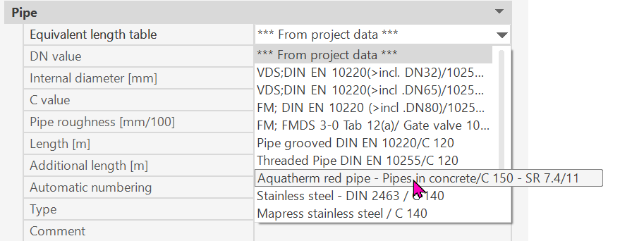
- Selection of the equivalent length table: either from the project management or a table specifically assigned to the pipe
Example: “Aquatherm”
- DN-Value: Diameter of the pipe, only diameters can be selected that are also defined in the current equivalent length table.
- Inner diameter [mm]: Shows the inner diameter from the equivalent length table.
- C-value: C-Value of the pipe (Hazen-Williams-formula)
- Pipe roughness: Roughness of the pipe, for calculation using the Darcy-Weisbach formula
- Length: Actual length of the pipe - Can be overwritten temporary for the calculation
Remark: Pipes can be entered shortened, e.g. the distance from the start to the end point of the pipe is (considerably) smaller than the actual length of the pipe in order to obtain a reasonable section when plotting. If the pipe has been entered with a shortened length, the following symbol appears in the pipe: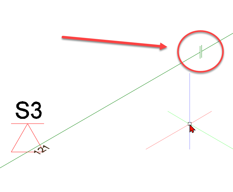
In this case the pipe must be entered shortened and the actual length of the pipe can still be read in the geometry category under "length".
- Additional length: is added to the actual length
The value for additional length is intended to take into account equivalent lengths for special components (e.g. reducer, throttle section, flexible hoses, etc.).
- Automatic numbering: If "yes", the next 2 input fields are hidden and the programme automatically assigns the pipe number. See also chapter Number pipes automatically
- Group number: (main) number of the pipe
- Element number: Sub-number of the pipe
- Type: Pipe type (not for branch pipes!)
The following applies to the pipe types
- F = riser/downcomer pipes
- V = Distribution pipes
- H = Main distribution pipes
- Z = supply pipes
The type of a pipe is not displayed for string pipes and cannot be changed.
- Comment: free text
- Category Fittings:
The program creates bended elbows, elbows and tees (as possible) automatically.
If more than 4 pipes meet in a node or if there are no right angles between the pipes, no elbows, bended elbows and tees can be created in this node.
In this case, the user must specify the fittings to be taken into account in the calculation here.
Of course, the fittings can be specified in any node. At the corresponding node, a label "E", "B" or "T" indicates whether a shaped piece was manually specified there.
Generally applies:
- "no fitting" is set -> the program distributes the fittings automatically.
- "elbow", "bended elbow" or "tee" is set -> fittings are set according to user specifications
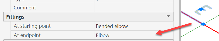
Visualization of the self-set fittings in the drawing at the beginning and end of the pipe:
Example of beginning of pipe:
see also chapter labeling pipes/sprinklers
- Category Calculation results: Properties in this category cannot be changed and show the results of the last calculation run.
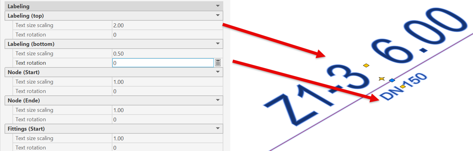
- Category Labeling:
You can edit labels individually or select multiple labels to edit them at the same time.
For example: “Top Label” is e.g. the pipe's designation
“Bottom Label” is e.g. the DN-value; depending on the perspective, the top and bottom labels may be reversed. Simply make the changes and test it.
Related topics:
Enter new pipes