Project Management
Icon:

Function: Modify/enter project data, drawing units, labeling, floors, groups, and define design areas.
Definition of calculation types.
After starting the program, a dialog box appears for entering project data and defining the equivalent length table that applies to the project:
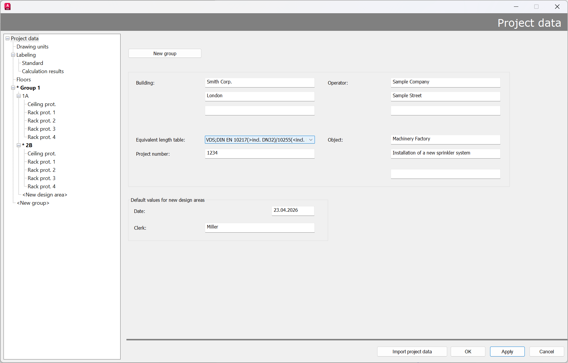
Most of these dialog boxes are simple text fields and not required for the calculation.
The text entries will appear in the header of the first page when the results are printed.
A new group can be created by clicking on “New Group”.
The following input is required for the calculation itself:
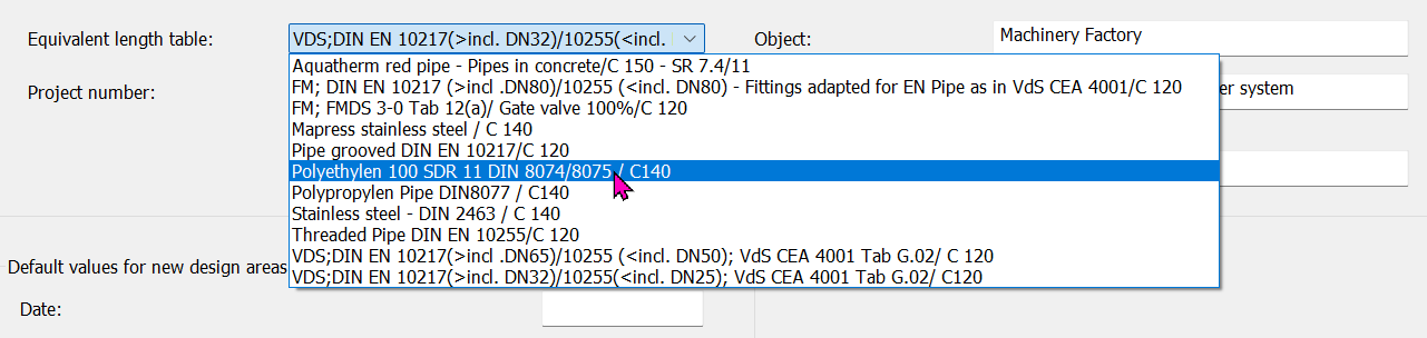
- Equivalent length table
Tables can either be used with mixed pipes or attached to a separate table for each pipe that contains only one pipe type.
Example:
Mixed table:

- Name code - IDAT Table:
VDS - Lengths of fittings according to VdS CEA 4001 -> Lengths of installation components have to be adjusted according to the manufacturer -> currently according to Table G.02
DIN EN 10217 Rohr (> incl. DN32) -> Inner diameter from DN 32 (included) -> corresponds to thin-walled grooved pipe up to DN 600
DIN EN 10255 Rohr (< incl. DN25) -> Inner diameter from DN 15 to DN 25 (included) -> corresponds to thick-walled threaded pipe
VdS CEA 4001 Tab. G02 -> See above
C-Wert für Hazen-Williams-Formel -> C120 for steel pipe; for informational purposes only
Self-defined tables can be selected from a list (in this case, the lists provided by IDAT):
Equivalent length tables can be edited and created using the SpriVor program described in the “Default settings” chapter.
Note: Since not all pipe types can be managed in the standard equivalent length tables, it is recommended that you always create your own suitable equivalent length table or enter the correct equivalent length for the specific make used in the project. The attached tables are adapted to the standard pipe types in sprinkler technology. The lengths of pipe elbows, tees, elbows threaded, etc., are taken from the VdS regulation (VdS-CEA 4001). Depending on the manufacturer, e.g., for alarm valve stations, the lengths may also vary.
Note: Pump performance curves are entered directly at the feed-in point or in the SpriCalc program after the calculation
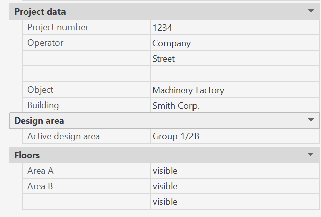
Some project management with sub-functions can also be changed via the properties palette without the dialog appearing.
The prerequisite is that no object is selected and at least one Pipe has been drawn.
Related topics: