Pipes/ Branch pipes
After selecting a pipe or branch pipe, "Advanced properties" can be opened in properties or via right-click in context menu:
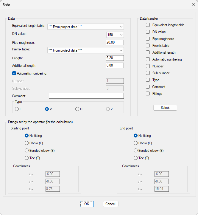
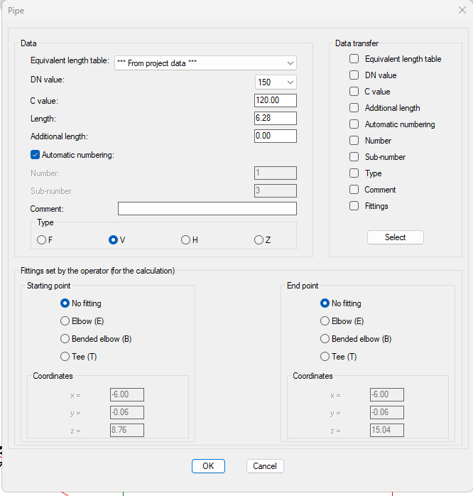
The dialog box consists of 3 sections:
1. Data: Non-geometric data of the pipes can be set in this section:
- Equivalent length table: In Project Management or individual single-variety tables
- DN Value: Diameter of the pipe (only eligible from values defined in current equivalent length table)
- C-value: C-Value of the pipe (Hazen-Williams-formula)
- Pipe roughness: Roughness of the pipe, for calculation using the Darcy-Weisbach formula
- Length: Actual length of the pipe
Pipes can be added with reduced lengths to ensure an appropriate section for the plot, if the distance between starting and end point is (significantly) shorter than the efficient length of the pipe. When adding the pipe with a reduced length, the following symbol will appear:
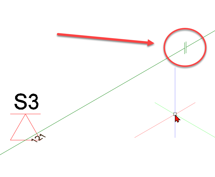
- Additional length: is added to the effective length
- Automatic numbering: If selected, "Number" and "Sub-Number" is deactivated and numbers are assigned automatically by the program (See Number pipes automatically)
- Number: (Main) Number of the pipe
- Sub-Number: Sub-Number of the pipe
- Comment: Free-form text field
- Type: Pipe type (not relevant for branch pipes!)
2. Fittings set by the operator (for the calculation):
(Bended) elbows and Tees are created automatically by the program, if possible.
If there are no right angles between the pipes or if more than 4 pipes meet in one node, angles, bends and tees cannot be created automatically in this specific node.
In this case, the user has to specify the fittings to be considered in the calculation.
Overall, Fittings can be specified in any node.
If fittings are specified in a node of one or more pipes, the program will only use the specified nodes for the calculation.
In general:
- If "No fitting" is checked
- The program will create Fittings automatically
- If "Elbow bended", "Elbow" or "Tee" is checked
- Fittings are set according to user specifications
Visualization of self-set Fittings in drawing at the beginning or end of the pipe:
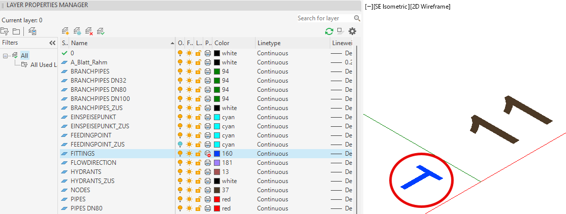
Layer FITTINGS: Select color. Default: Yellow (See also Labeling/Standard)
The coordinates of starting and end point in "Advanced properties" are for informational purposes only and cannot be changed.
3. Data transfer:
The (branch) pipe data can be transferred (completely or partially) to other (branch) pipes. In this regard, the parameters to be transferred has to be determined.
The following contents of the dialog box can be transferred:
- Equivalent length table
- DN Value
- C Value
- Additional length
- Automatic numbering (The current status of the object will be transferred, whether automatic numbering is active or inactive)
- Number (The main number of the current object will be transferred)
- Sub-number (The sub number of the current object will be transferred)
- (Pipe) type (no branch pipes)
- Comments
- Fittings
By clicking once, a value is registered for transfer (a check mark appears in the box), by clicking twice, the value is unregistered (the box is empty again).
Clicking the Select button triggers the transfer of the data (selected at this point).
The dialog box will be hidden and the user will be asked to select the pipes/branch pipes for which data are to be replaced.
The selection is made according to the procedure described in Selection/ modify of components.
After the selection is finished, the data will be transferred to the selected elements and the dialog box of the branch pipe will be shown again.
If the dialog box is left by Cancel, the modification of the branch pipe is terminated without accepting the changes.
After leaving the dialog box by pressing OK the altered data is accepted and the pipe is relabeled.
Note: Only data within one object group can be transferred:
- e.g. Sprinkler to sprinkler; pipe to pipe.
- e.g. Distribution pipe (V) to branch pipe (R) does not work
Related topics: