Enter gate valves, flaps, valves
Icon:

This menu option allows you to enter valves, gate valves, butterfly valves, and other fittings.
After selecting the command, the following input options appear in the properties palette:
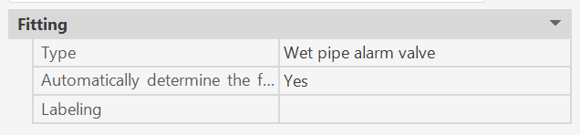
Each fitting is assigned the properties specified here. The data can be modified at any time during the command sequence.(*1)
The following appears in the command line:

- U: Undo the last action.
After selecting a pipe or branch pipe:
 (*2)
(*2)
or
 (*2)
(*2)
For information: Depending on which point is closer to the selected point when choosing a pipe, that point serves as the starting point for entering the symbol (indicated by a flexible line at the cursor).
Depending on the selection, one of the two prompts will then appear.
(*2)
The minimum distance from a node to a component is set to at least min. 0.01 m or 1 cm and cannot be placed directly within the node; it must be placed at a greater distance from the start node. The reason for this is that components must always be assigned a fixed dimension for the calculation. If they were placed within a node, the component would always be assigned the smaller dimension in the flow direction. In that case, the equivalent length of the fitting might be assigned to the wrong pipe or dimension. The fitting always takes on the dimension of the pipe to which it is assigned.
For valves, gate valves, and check valves, equivalent lengths are listed in tables for use in hydraulic calculations.
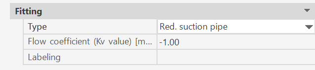
If a selected fitting is not listed in the equivalent length table, you must specify a custom equivalent length.
This must then be entered directly. Default value -1 -> Component cannot be set.
Warning message:
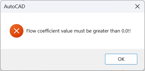
Even before the calculation, the program highlights zero values in the components.
The fitting is created on the pipe at the specified distance from the starting point toward the end point, or from the end point toward the starting point.
SpriCAD offers the following symbols:
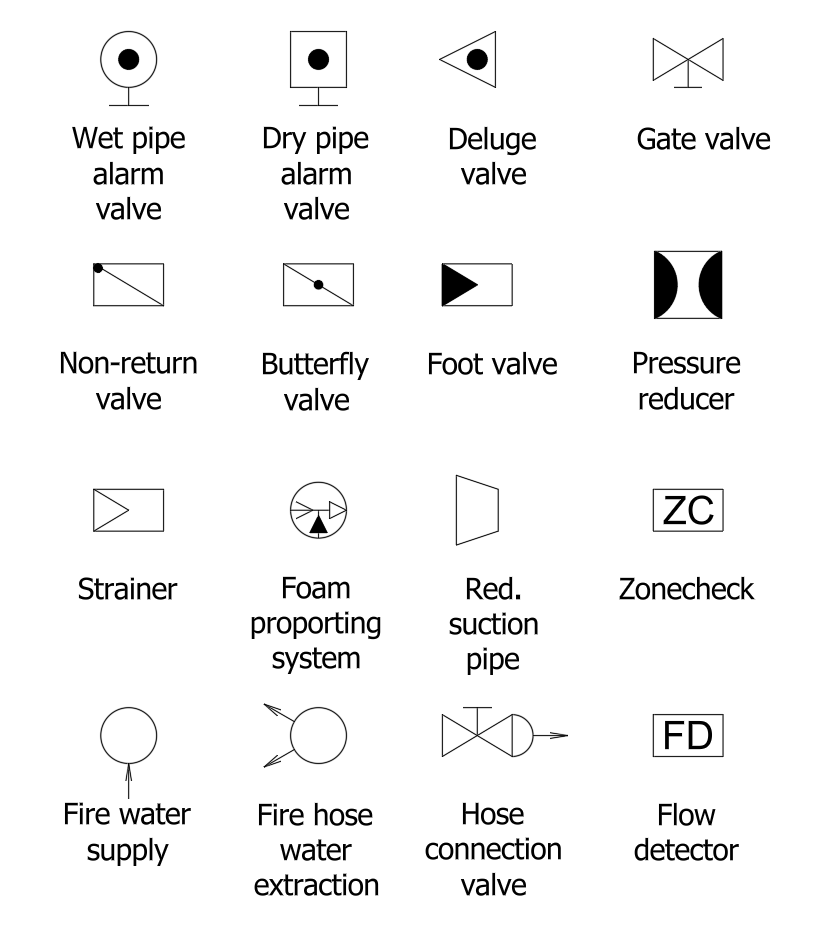
These symbols are defined in the “Symbol.cfg” file (see also the section on the symbol file) and can be modified as needed.
This makes it easy to add new fittings.
(*1)
If the value of the CAD system variable COMMANDPROPERTIES is 0, nothing is displayed in the properties palette; instead, the properties dialog for fittings (Fitting Properties dialog) appears at the end of the command.
Related topics: