Cover area with sprinklers
Symbol:

Input of any closed polygon whose interior is automatically filled with sprinklers.
After starting the command, the following dialog box appears:
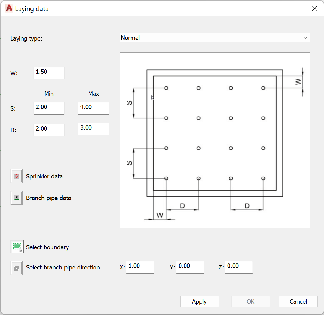
- Laying type
Here you can select one of the two installation types Normal or Shifted. The picture shows an example of the type of installation.
- W, S, D
Enter the minimum and maximum distances between the sprinklers. The meaning of the values can be taken from the respective laying picture.
- Sprinkler data
This button can be used to specify the data for the sprinklers to be installed. After selecting this button, the dialog box for entering the sprinkler data (sprinkler properties dialog) appears.
- Branch pipe data
This button can be used to specify the data of the branch pipes to be laid. After selecting this button the dialog box for entering the branch pipe data (branch pipe properties dialog) appears.
- Select boundary
After selecting this button the dialog box is hidden and the prompt to select a polyline appears:
Select polyline:
You can select any closed AutoCAD/ BricsCAD - polyline (AutoCAD command POLYLINE).
After the selection is completed, the dialog box for entering the laying data is displayed again.
- Select branch pipe direction
Allows to select or directly enter the direction of the branch pipes to be laid. After selecting the button, the dialog box is hidden and the prompt for entering a direction appears:
Specify direction [base point/X/-X/Y/-Y/Z/-Z/Angle/Space angle] <X>:
(See Input of a direction)
After leaving the dialog box with OK, sprinklers and branch pipes are generated according to the data entered.
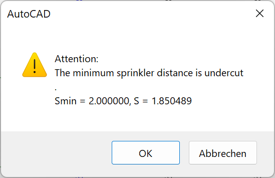
Note: In case of falling below the minimum sprinkler distance that has been set, the program informs via a message.