Mode of operation
The third tab of the project data contains inputs for the calculation like mode of operation.
The following inputs are required for the calculation:
- Pipe diameter and equivalent lengths
Either one of the following tables can be used
- VDS;DIN EN 10220(>incl. DN32)/10255(<incl. DN25) welded.; VdS CEA 4001 Tab G.02/ C120
- VDS;DIN EN 10220(>incl .DN65)/10255 (<incl. DN50) seemless; VdS CEA 4001 Tab G.02/ C120
- FM; DIN EN 10220 (>incl .DN80)/10255 (<incl. DN80) - Fittings adapted for EN Pipe as in VdS CEA 4001)/C120
- FM; Schedule 40, FMDS 3-0 Tab 12(a)/ Gate valve 100%/C120
or a separate table can be created.
Note: Not all pipe types are included in the standard equivalent length tables.
It is therefore advisable to create your own table.
The attached tables are intended for common pipe types in sprinkler technology, while equivalent lengths for pipe bends and elbows have been taken from the VdS regulation.
The lengths of the components may vary depending on the manufacturer, particularly in the case of alarm valve stations. Information on component lengths can be found in the manufacturer's documentation.
The values in our table are only rough guidelines for initial planning.
Please take the equivalent lengths according to the manufacturer's specifications into account in the final calculation.
- plant type
One of the following system types must be selected ( the equivalent lengths of the alarm valve stations are taken from the equivalent length table here by your selection):
- Wet system
- Dry system
- Quick dry system
- Pilot-operated dry system
- Tandem system
- Deluge system
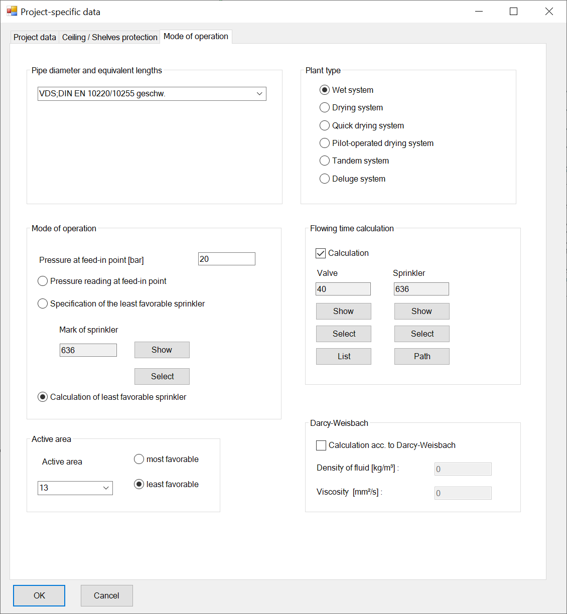
- Mode of operation
Enter a working method for your calculation.
In order to provide the pipe network with sufficient pressure for the calculation, leave 20 bar as the pressure at the feed point until you know how much feed pressure you need.
There are 3 types of calculation available.
- Active area:
Each sprinkler can be added to any active area number.
This input field determines which active area is calculated during the next calculation run.
Specify whether you want to calculate the favourable or most unfavourable active area.
This is then marked in the calculation printout.
- Flowing time calculation:
Calculate the flow time from a valve to the worst sprinkler e.g. for dry groups. Not applicable for meshed networks.
The valve from which the calculation is to be made must be entered in the shut-off valve list in advance.
Click on List in the project data
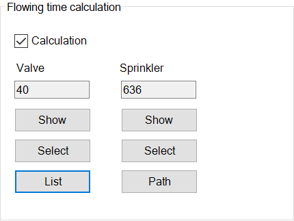
it appears
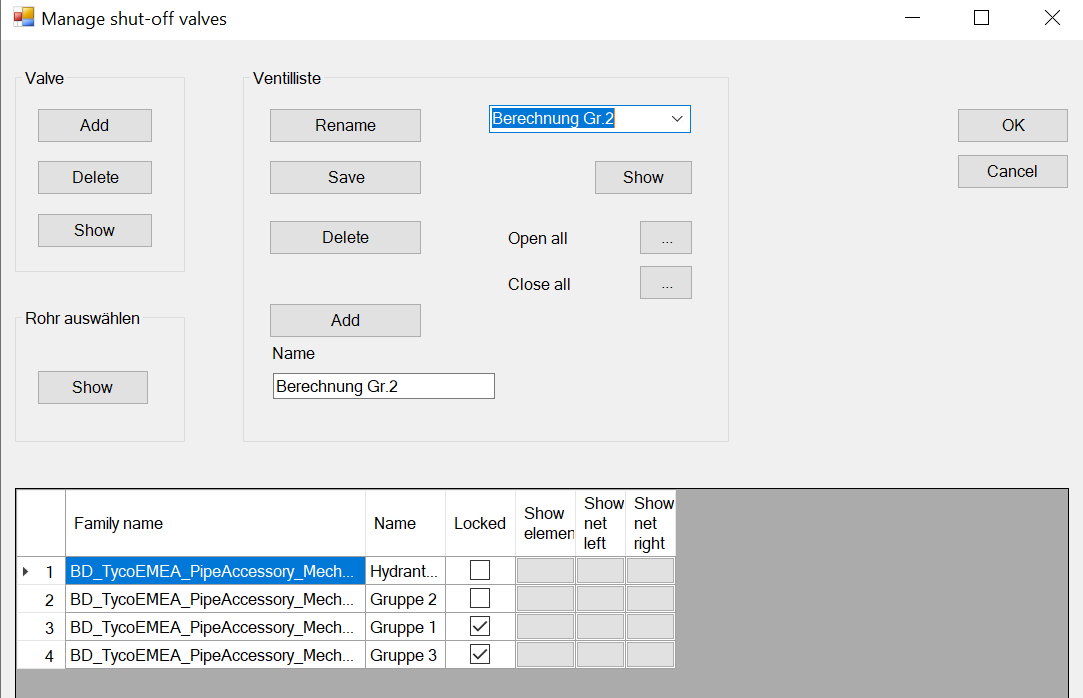
Select the valve in the drawing and click on Add. The valve appears in the list.
Close the dialogue with OK.
The valve is now selected for the flow time calculation.
You can also select the valve in the drawing and then add it by Select. However, it must always be entered in the valve list beforehand.
Then select the sprinkler that is intended for the flow time calculation and click on Select.
The sprinkler number, assigned internally by the programme, is entered automatically.
Click on OK.
The flow time is then displayed in the report after a new calculation at the sprinkler.

The button path shows in the drawing the saved path of the route to be calculated in the model. The objects are marked in colour blue in the drawing.
Note: If the error message "Sprinkler and valve do not belong to a subnetwork" appears and all settings in project management, effective area and feed point are correct, use the "Refresh" button to correct the error.
Check also project admin.
Related themes:
- Darcy-Weisbach
Normally, the pressure loss in the pipe network is calculated SpriCAD® is using the Hazen-Williams formula.
However, this formula can only be used for water.
This is not possible for pipes which are completely filled with a water/foam mixture.
In this case, the formula according to Darcy-Weisbach must be used.
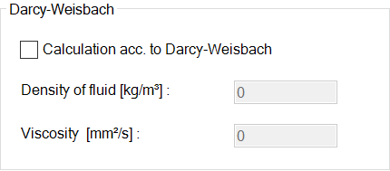
This type of calculation is a chargeable additional module and is not included in the standard scope of delivery.
The material parameters fluid density (in kg/m²) and viscosity (in mm²/s) of the medium are required.
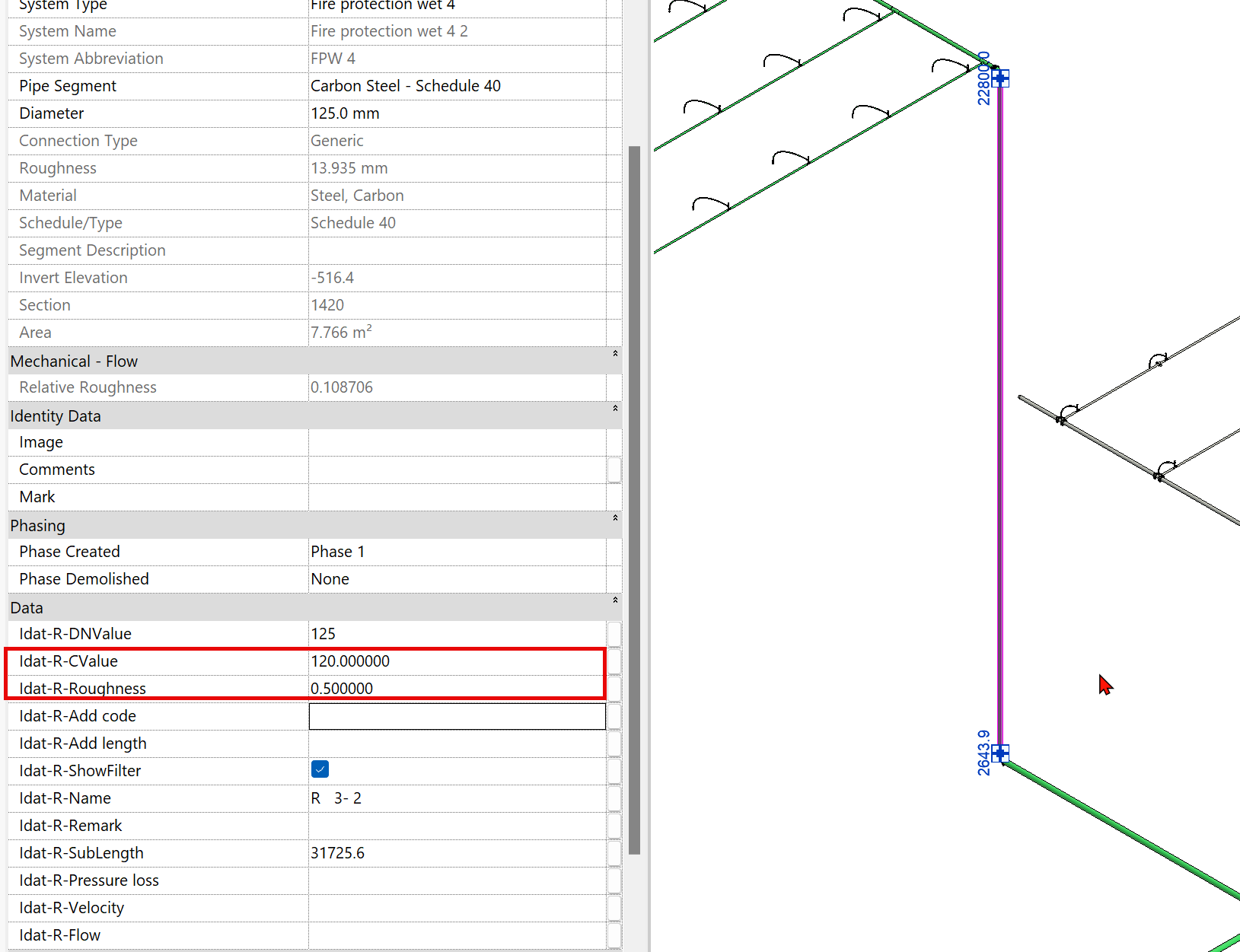
With the Darcy-Weisbach formula, the pipe roughness must be specified directly.
With the Hazen-Williams formula, on the other hand, the roughness is indirectly included in the C-value of a pipe.
This means the following: If it is a foam extinguishing system, the pipe roughness must be specified in 1/100 mm for all pipes instead of the C-value.
Example: If the pipe roughness for steel pipes is 0.5 mm, the value must be entered in IDAT-R-Roughness for this pipe and the C-value 4,5 for stainless steel 0.045 mm. (Source: VdS CEA 4001).
Set the correct value for the pipe roughness.
Here steel pipe: