Shut-off valves
Symbol:

Function: Shut off areas within a file to speed up the calculation.
Use butterfly valves, gate valves or alarm valves to shut off areas.
Any family defined in Revit as pipe accessories and part type valve can be selected.
After starting, the dialog box for entering shut-off valves appears:
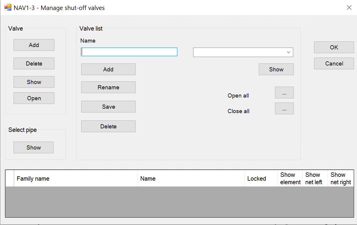
- Valve
Click on a valve in the drawing and click on Add.
If you want to delete the valve from the list, select it and click on Delete.
The Show button requires you to first select a valve in the drawing that has already been added to the list, then it will be marked in the list.
Open the valve directly by the button if it was previously closed.
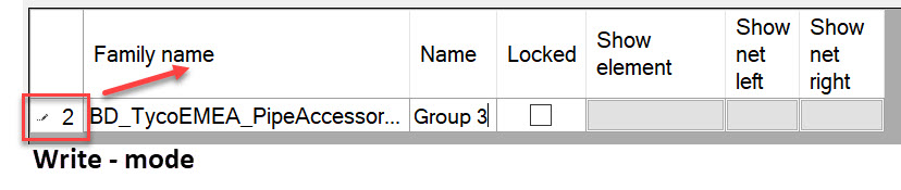
Give your valve a unique name in the list, e.g. group 3.
Shortly after that click on the table name and the name will be saved.
The pen at the beginning of the line disappears.
After that its saved:
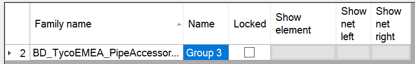
Click on the grey field to the right of the entry. Here you can also display the element from the list in the model.
Show net left shows all elements after the valve; show net right shows all elements before the valve.
This allows you to keep an overview.
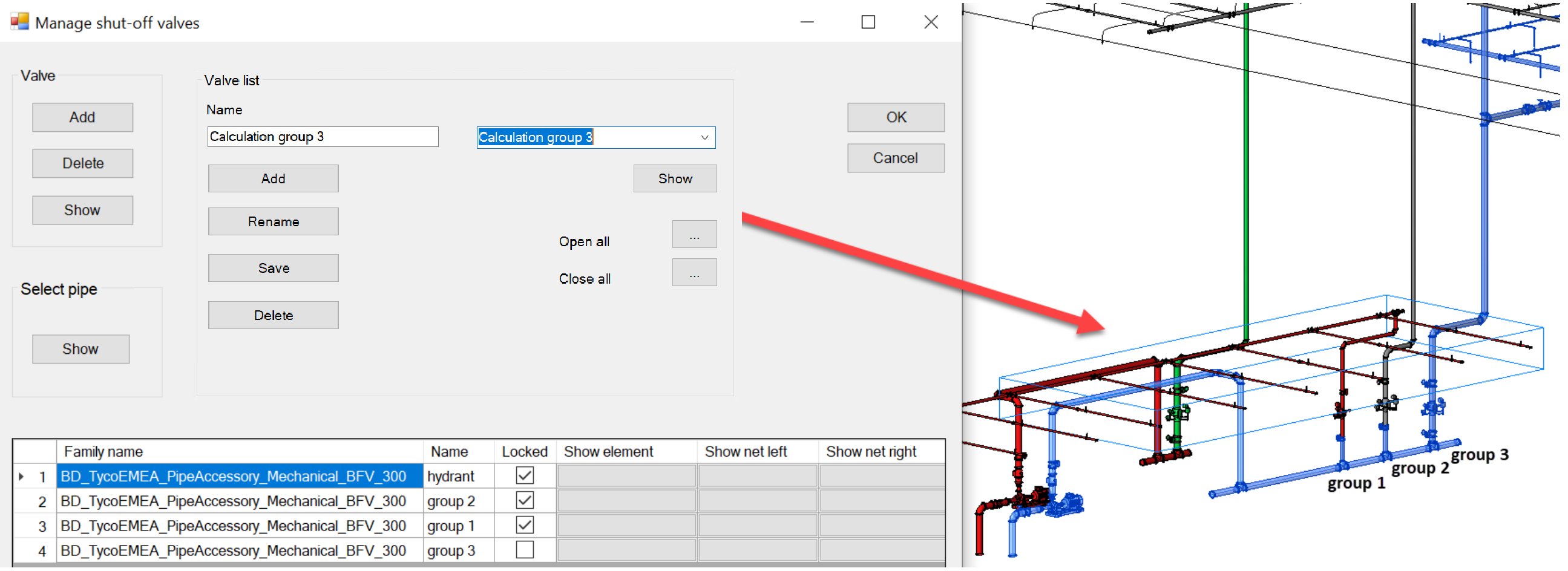
- Valve list
If you want to manage several valves, you can also store valve lists here (e.g. calculation gr. 3)
Check the boxes for the valves to be shut off and then enter a name for the list as in the example above.
Then click on Add. The name of the list appears in the field at the top right.
If you click directly Save, the list is saved immediately, otherwise it is always saved by OK.
If you want to rename a list, first change the name in the name field at the bottom.
Then click on Rename. Now the list is renamed in the top right field.
The functions Open all/Close all, open or close all valves from this list simultaneously.
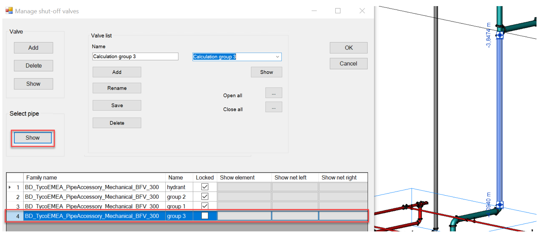
The function Show under the pipe lists, shows in colour which areas are closed off and which are not.
Make sure that no element is selected here before starting the function.
The areas that are not blocked off are marked in blue, as can be seen in this example.
- Select pipe
Select any pipe in your network in the drawing file and click on Show.
The group it belongs to will be highlighted in blue.