Cover area with sprinklers
Icon:

Selection of any closed polygon whose interior is automatically filled with sprinklers.
After executing this command, the following dialog box appears:
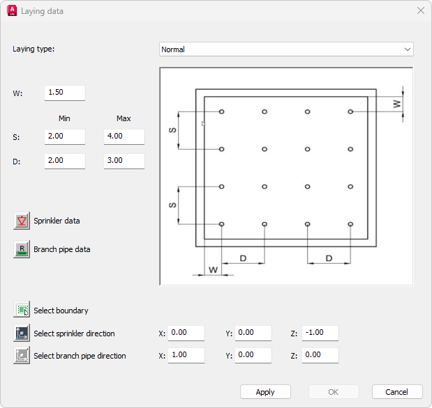
- Laying type:
One of two installation types can be set: Normal or Shifted. The screenshot shows an example of this type of installation.
- W, S, D:
Minimum and maximum distances between the sprinklers are entered. The meaning of the values can be taken from the respective laying picture.
- Sprinkler data:
This button can be used to specify the data for the required sprinklers. The dialog box for entering the sprinkler data (Sprinkler - properties dialog) appears after clicking on the icon.
- Branch pipe data:
This button can be used to specify the data of the required branch pipes. The dialog box for entering the branch pipe data (Branch pipes -properties dialog) appears after clicking on the icon.
- Select boundary:
After selecting this button the dialog box is hidden and the prompt to select a polyline appears:

Any closed AutoCAD/ BricsCAD - polyline can be selected (AutoCAD command POLYLINE).
After the selection is completed, the dialog box for entering the laying data is displayed again.
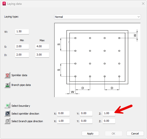
- Select sprinkler direction:
Allows selecting or directly entering the direction of the required sprinklers. After selecting the button, the dialog box is hidden and the prompt for entering a direction appears:

(See also Entering a direction)
Specify direction, e.g. Z: Sprinklers are displayed upright
- Select branch pipe direction:
Allows selecting or directly entering the direction of the required branch pipes. After selecting the button, the dialog box is hidden and the prompt for entering a direction appears:
Specify direction [base point/X/-X/Y/-Y/Z/-Z/Angle/Space angle] <X>:
(See also Entering a direction)
After leaving the dialog box with OK, sprinklers and branch pipes are generated according to the data entered.
Note: In case of falling below minimum sprinkler distance that has been set, the program displays a message.