Project data
Symbol:

Input of project data.
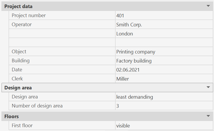
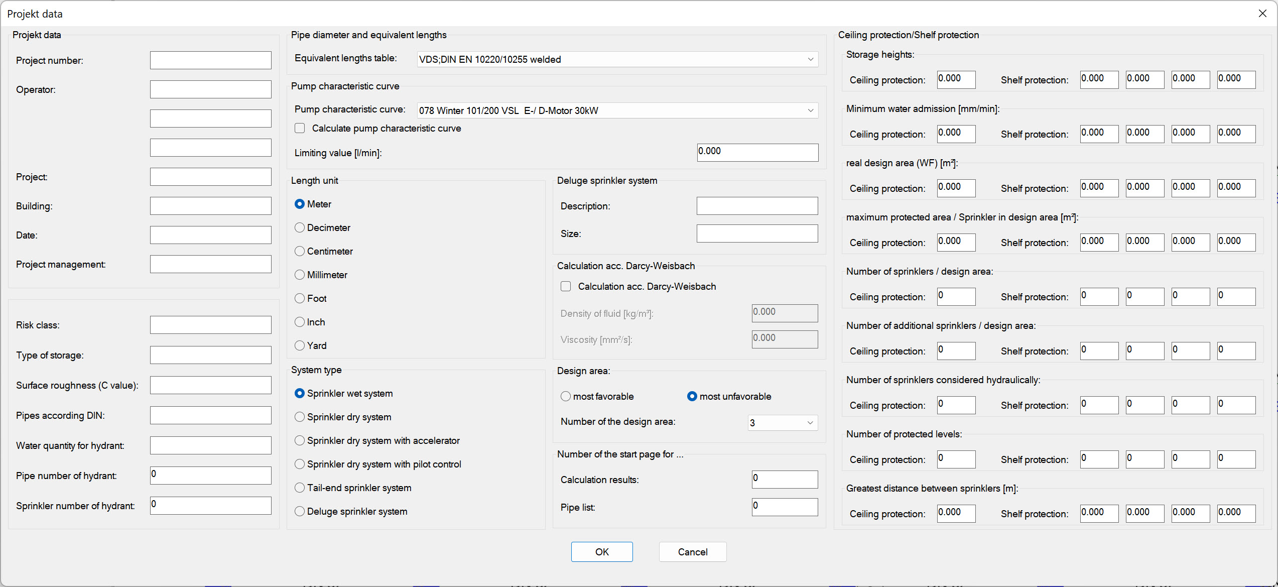
After starting, the dialog box for entering project data appears:
Most of these dialog boxes are only text fields and are not needed for the calculation.
When the results are printed, the text entries are output in the header of the first page.
The following inputs are required for the calculation:
- Pipe diameter and equivalent lengths
You can use one of the following tables
- VDS;DIN EN 10220(>incl. DN32)/10255(<incl. DN25) welded.; VdS CEA 4001 Tab G.02/ C120
- VDS;DIN EN 10220(>incl .DN65)/10255 (<incl. DN50) seemless; VdS CEA 4001 Tab G.02/ C120
- FM; DIN EN 10220 (>incl .DN80)/10255 (<incl. DN80) - Fittings adapted for EN Pipe as in VdS CEA 4001)/C120
- FM; Schedule 40, FMDS 3-0 Tab 12(a)/ Gate valve 100%/C120
or, if own tables have been defined.
Editing and creation of equivalent length tables is done with the program SpriVor described in chapter Preferences.
Note: Not all pipe types are included in the standard equivalent length tables.
It is therefore advisable to create your own table.
The attached tables are intended for common pipe types in sprinkler technology, while equivalent lengths for pipe bends and elbows have been taken from the VdS regulation.
The lengths of the components may vary depending on the manufacturer, particularly in the case of alarm valve stations. Information on component lengths can be found in the manufacturer's documentation.
The values in our table are only rough guidelines for initial planning.
Please take the equivalent lengths according to the manufacturer's specifications into account in the final calculation.
- Pump characteristic curve:
By clicking on the rollup-menu in this dialog box, a list of the entered pump types is displayed from which a pump type can be selected.
Editing of pump curves andcreate new pump curves can be done with the SpriVor program described in chapter Default settings.
- Length Unit
The unit of draw is fixed in advance.
You can select meter, decimeter, centimeter, millimeter, foot, inch and yard.
Drawings can now also be rescaled afterwards.
Procedure:
- Attach the drawing that is to be scaled to a new file template as a reference.
- Bind the reference file and scale the block to the desired dimension e.g. from m with factor 1000 to mm
- Set block with the function "explode" in the origin - afterwards texts adapt themselves automatically!
- mm is now automatically displayed in the project data.
- System type
You must select one of the following system types:
- Sprinkler wet system
- Sprinkler dry system
- Sprinkler dry system with accelerator
- Sprinkler dry system with pilot control
- Tail-end sprinkler system
- Deluge sprinkler system
Foam extinguishing system
Normally, the pressure loss in the pipe network is calculated according to the Hazen-Williams formula.
However, this formula can only be used for water.
This is not possible for pipes that are completely filled with foam concentrate.
In this case the Darcy-Weisbach formula must be used.
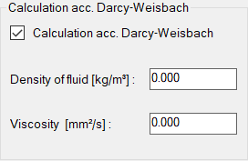
This type of calculation is an additional module that is subject to charge and is not included in the standard scope of delivery.
The material parameters density of fluid (in kg/m²) and viscosity (in mm²/s) of the medium are required.
With the Darcy-Weisbach formula, the pipe roughness must be specified directly.
In contrast, in the Hazen-Williams formula, the roughness specified by the C-value of a pipe.
This means : If it is a foam extinguishing system, the pipe roughness must be specified in 1/100 mm for all pipes instead of the C-value.
Example: If the pipe roughness for steel pipes is 0.5 mm, the number 50 must be entered as the C-value for this pipe and the C-value 20 for stainless steel 0.2 mm. (data source VdS CEA 4001)
- Length Unit
The unit of draw is fixed in advance.
You can select meter, decimeter, centimeter, millimeter, foot, inch and yard.
Drawings can now also be rescaled afterwards.
Procedure:
- Attach the drawing that is to be scaled to a new file template as a reference.
- Bind the reference file and scale the block to the desired dimension e.g. from m with factor 1000 to mm
- Set block with the function "explode" in the origin - afterwards texts adapt themselves automatically!
- mm is now automatically displayed in the project data.
- Number of the active area:
Each sprinkler can be added to any protection area.
This input field determines which protection area will be calculated in the next calculation run.
The sprinklers in the protection area are shown in red.
Here you can specify in advance that, for example, number 1 is the most unfavourable active protection area.
Only the design areas, that are defined in the project, are displayed.
Some project data can also be changed without opening the dialog by the properties palette.
The prerequisite is that no object is selected and at least one pipe has been drawn.